
Custom Machining Parts vs. Alternatives: Choosing the Material–Process Pair That Fits the Part
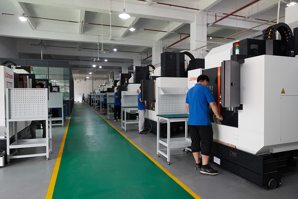
Custom machined parts sit at the center of a material–process–finish chain: the material decides the process that cuts it, the process decides the tolerance it can hold, and the finish decides what the surface becomes afterward. Before any of that chain starts, a harder question has to be answered — should this part be machined at all? Metal 3D printing, die casting, forging, and injection molding each win a specific corner of the part universe, and each one hands work back to a machining floor for its critical features. This guide compares the realistic alternatives to custom CNC machining from a buyer's side: which process takes over at which quantity and geometry, what each one can and cannot hold, and what each route has to prove before you commit a drawing and a budget.
Why is the material–process pair the first decision on a custom part?
A drawing does not arrive labeled "machine this." It arrives as a set of requirements — a function, a quantity, a set of loads, an environment — and the buyer's job is to pair a material with a process that meets them. The pairing matters because the two halves constrain each other. A free-machining alloy like 6061 aluminum cuts fast and finishes well, so it pairs naturally with machining at almost any quantity. A thin-walled housing that must come off a die at high volume pairs with a casting alloy and accepts cast tolerances. A load-bearing link that needs grain aligned with its shape pairs with a forging and then with machining on its ends.
The verification half is what buyers of custom parts often miss. Sourcing from a supplier — in China or anywhere — means every claim on the drawing has to be checked against evidence, and the process decides what that evidence looks like. Machining from certified solid stock produces a clean trail: mill certificate, XRF check on arrival, CMM report on the dimensions. A printed part needs powder and build-direction evidence for its mechanical properties. A casting's porosity cannot be seen from the surface. So the process decision is partly a verification decision, and the comparison below keeps both halves in view.
Which custom parts should stay on the machining floor at any volume?
Some parts belong to machining regardless of quantity, and naming that set first keeps the comparison honest:
- Parts with a real tolerance. Milling and turning hold ±0.003 mm on this floor, with ±0.002 mm available on precision-ground surfaces. A bearing seat, a sealing face, or a press-fit diameter at that level cannot be printed, cast, or molded into tolerance — the alternative processes land a class or two looser, so the part is a machining part by requirement, not by preference.
- Parts that must be a specific wrought material. If the drawing calls 6061-T6, 7075-T6, 17-4 PH, or a titanium grade, the material state comes from certified solid stock. A printed or cast version of the same alloy is a different material with different properties, and the drawing's claims no longer hold.
- Parts in low-to-mid volume. With no mold or die to amortize, the MOQ is one piece and per-part cost stays roughly flat from prototype into production. Machining is the only process that behaves this way.
- Parts with features across several material families. A floor running 100+ machines — 50+ 3-axis, 20+ 4-axis, and 20+ 5-axis milling centers, 25+ lathes, and 7+ grinders — machines aluminum, steel, stainless, brass, copper, and titanium without changing process, which lets a buyer change material during development without re-tooling.
Everything outside this band is a candidate for an alternative, and the candidate should be compared on quantity, geometry, and tolerance, in that order.
When does metal 3D printing take a part off the machining floor, and when does it hand back?
Metal additive manufacturing owns the geometry that cutting tools cannot reach. Internal cooling channels, lattices, organic shapes, and conformal features are printed because no toolpath can produce them. At one-to-ten-piece runs of that geometry, printing is often faster and cheaper than machining — there is no fixture fight, no scrap from a billet, and a design revision costs a file change rather than a setup change. For development and validation parts, that speed is the whole point.
The hand-back is equally specific. Printed metal is not wrought metal: the powder-bed process leaves anisotropy, lower fatigue strength in some directions, and a rough as-built surface. Tolerances on printed features typically land in the ±0.1–0.5 mm range — a class or two looser than machining — so the surfaces that must seal, bear, or locate go to a cutter or a grinder after printing. Threads in printed holes are unreliable without machining or an insert. And the verification chain changes: instead of a mill certificate plus XRF, a printed part needs its powder lot, build parameters, and mechanical property evidence documented.
The buyer's takeaway: treat 3D printing as a geometry and iteration tool, not as a way to get machined properties faster. Print the internal complexity, machine the functional faces, and verify the material with the same rigor you would apply to any metal part. For a part that is mostly a bracket or a shaft, printing is the expensive route to a worse result.
When does die casting win a housing, and what comes back to the machine?
Die casting is the high-volume answer for thin-walled, net-shape housings and enclosures. The die produces a finished shell in seconds, and once the tooling is amortized the per-part economics beat machining outright. A machined aluminum housing is competitive at a few hundred pieces; the same housing at tens of thousands is a casting conversation. Casting also consolidates: what would be several machined pieces can merge into one cast body with bosses, ribs, and mountings formed in.
What casting cannot deliver is machining tolerance or wrought properties. Draft angles are built into the die, so walls taper and parallel features need a secondary cut. Porosity is inherent — internal voids that can surface during machining and that fatigue-loaded parts cannot accept. The verification question shifts from "is the alloy right" to "how is porosity controlled and inspected, and which faces are machined after casting."
The practical answer for precision work is a hybrid: cast the body at volume for its thin walls and low cost, then machine the faces that seal, locate, or carry a bearing back to a real tolerance. The quote should show both steps, because a casting-only price hides the machining that the drawing still needs.
When does forging earn the part, and what proof does it carry?
Forging is specified when a part must carry load through its grain structure. Machining from bar cuts across the grain; forging aligns it with the part's shape, which buys fatigue life and impact toughness that bar stock cannot match. Connecting rods, suspension links, valve bodies, and gear blanks are forged for exactly that reason.
A forged part is really two parts in sequence: a forged blank that arrives near-net-shape with generous variation, and machined features — bores, faces, threads, and locating surfaces — cut afterward on a machining floor. The buyer's verification therefore has two halves. The forging half is the heat number, chemical composition, and mechanical test results from the forging house, read against the standard the drawing names. The machining half is the same CMM and XRF evidence any machined order carries. A supplier that can machine the forging in-house closes the whole chain under one roof; one that buys blanks from an unnamed third party adds a hand-off you cannot audit.
When does injection molding take over a plastic part, and what happens to its tolerances?
Injection molding is the volume answer for plastic parts. Once the mold exists, each shot produces a finished part in seconds, and at high volume the per-part price falls below anything machining can reach. Molding also makes thin, uniform walls and complex polymer geometry that would be impractical to cut. For enclosures, housings, and high-volume plastic components, the mold wins.
The cost of that win is mold money, mold lead time, and tolerance. A mold is a real investment and real weeks before the first part exists, so molding pays off only at volume. Molded tolerances are set by polymer shrinkage, which varies with material and wall thickness — typical molded features land in the ±0.1–0.5 mm range, not at machined precision. A molded part that needs a tight bore, a true flat face, or a precise datum gets those features machined afterward. The material choice compounds this: amorphous plastics like ABS shrink differently from semicrystalline ones, and glass-filled grades behave differently from unfilled.
The honest comparison against machining is total program cost: mold cost plus per-part price at your quantity, versus machining's no-tooling per-part price. The crossover is at high volume for simple plastic parts. When the part needs tight plastic features, the practical answer is a molded body with machined critical faces — the same hybrid logic as die casting, applied to polymers.
How do you put the alternatives on one comparison sheet?
The comparison that survives an RFQ is a table scored on the dimensions that actually change the decision:
| Dimension | CNC machining | Metal 3D printing | Die casting | Forging | Injection molding |
|---|---|---|---|---|---|
| Best quantity | 1 to low thousands | 1–10 iterations | High volume | Medium–high volume | High volume |
| Tolerance | ±0.003 mm (grind ±0.002) | ±0.1–0.5 mm typical | Cast tolerance + draft | Near-net; machined after | ±0.1–0.5 mm shrinkage-driven |
| Material integrity | Wrought, certified stock | Powder-bed, anisotropic | Porosity possible | Grain-aligned, strong | Polymer, shrinkage |
| Tooling | None | None (high per-part) | Die — amortizes | Die — amortizes | Mold — amortizes |
| Best geometry | Prismatic, round, tight features | Internal channels, lattices | Thin-wall shells | Load-carrying shapes | Thin-wall plastic shells |
| Verification | Mill cert + XRF + CMM | Powder + build evidence | Porosity + machined faces | Forging cert + machined features | Shrinkage + machined critical features |
Score your own part against the table before you send a drawing: mark the quantity band, circle the tolerance that matters, and name the one or two features that cannot fail. The process that survives all three is your answer, and when the answer is a hybrid, as it often is, the RFQ should ask for the full chain rather than one process's half of it.
What does the winning route need to prove?
Once the material–process pair is fixed, the evidence question follows the same discipline this site applies to every claim: name the proof before you commit. The material-selection guide on this site shows which metal families machine cleanly and what each one needs to have verified; the process comparison adds the alternative routes' own evidence.
- A machined part ships with the mill certificate read against the standard, the XRF record for incoming stock, CMM reports on critical dimensions, and SPC data where process capability matters — the trail this factory runs on every lot.
- A printed part needs powder-lot and build-direction documentation plus mechanical property evidence, because its material is not the same as wrought stock of the same name.
- A casting needs its porosity control stated and its post-cast machined faces identified.
- A forging needs its heat number and mechanical test results traced to the standard.
- A molded part needs its shrinkage assumption and its machined critical features on record.
The drawing names the material and tolerance; the supplier names the evidence that proves both, before the quote becomes an order. The quality verification page details how the machined half of that evidence is produced and documented, so you can read the reports that arrive with the parts against the floor that made them.
Frequently Asked Questions
When should a custom part be machined instead of 3D printed?
Machine it when the part needs a real tolerance (milling and turning hold ±0.003 mm here), a certified wrought material, or more than a handful of pieces. 3D printing earns its place on internal channels, lattices, and fast design iteration at one-to-ten-piece runs. For a straightforward bracket or shaft, machining is usually cheaper and delivers the material integrity the drawing assumes.
At what quantity does die casting beat machining?
The crossover is set by tooling amortization, not by a universal part count. Add the die cost to the casting per-part price and compare the total against machining per-part at your volume; the point where casting wins is where the die has paid for itself. Thin-walled housings that cut slowly often cross over within a few thousand pieces, while fast-machining simple parts may stay cheaper as machined for much longer.
Can a die-cast part hold machined tolerances?
Not as-cast. Die casting gives net-shape geometry with draft angles and possible porosity, so tolerances are cast-grade. The features that must seal, locate, or carry a bearing are machined after casting to reach a real tolerance, which is why the hybrid of a cast body with machined critical faces is the honest answer for precision housings.
Is a forged part always stronger than a machined one?
Forging aligns grain with the part's shape, which can buy fatigue life and impact toughness that machining from bar does not provide. But the forged blank still needs machining on its functional surfaces, so a forged part is a forged blank plus machined features. Choose forging when the design needs load-carrying grain structure; the machining half still produces the precision.
When does injection molding make sense over machining a plastic part?
At high volume, once the mold cost amortizes and each shot undercuts machining per-part. Molded tolerances are shrinkage-driven, typically ±0.1–0.5 mm, so tight features are machined afterward. For simple plastic parts at low volume, machining from plate or bar is usually faster, cheaper, and free of tooling cost.
Does a printed metal part match machined strength?
Not automatically. Printed parts carry the powder-bed process's properties — anisotropy, direction-dependent fatigue strength, and surface roughness that often needs machining on critical faces. Treat a printed part as a different material from wrought stock until its mechanical property evidence says otherwise; machining from certified stock starts from the mill certificate.
What documents should the chosen process ship with?
Every route has to prove the two things the drawing claims: the material and the tolerance. Machining proves them with a mill certificate read against the standard, the XRF record for incoming stock, and CMM reports on the critical dimensions. The alternatives prove them differently — printed parts carry powder-lot and build-direction records, castings state their porosity control, forgings trace a heat number and mechanical tests, and molded parts record their shrinkage assumptions. Whatever the route, request that evidence list with the quote; a supplier that commits to documents up front is one whose process claims you can audit.
Deciding between custom machining and an alternative process, and not sure what the winner should prove?
Send the drawing and the quantity. We will come back with the process comparison for your geometry, the tolerance each option can realistically hold, and the verification documents buyers should expect from the chosen route. Email [email protected] or call +86 13126536955.